Chapter 8 - Custom graphics - a circle
Updated to Gio 0.8.0 as of April 4th 2025
Goals
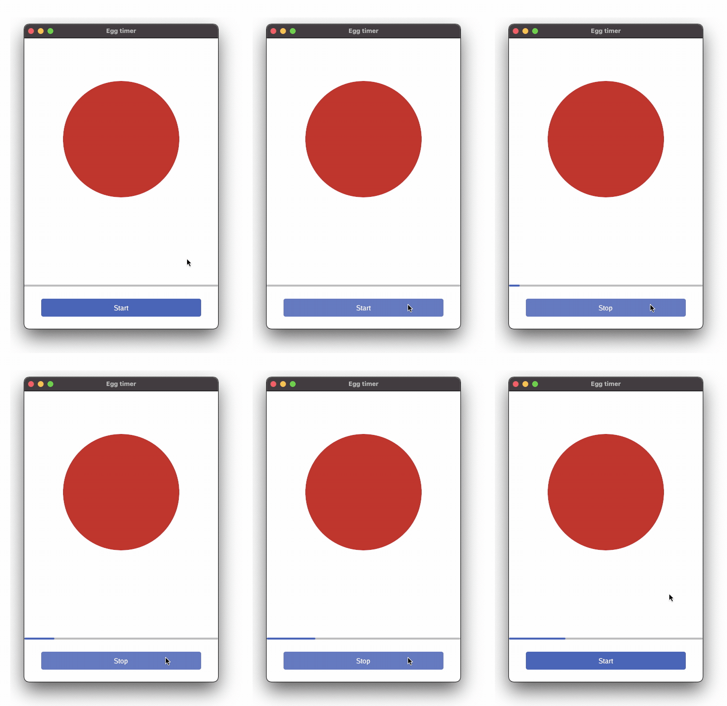
The intent of this section is to draw custom graphics that (vaguely) resembles an egg

Outline
The code introduces custom graphics. The circle in the app is drawn by Gio, not displaying a static picture. Tho achieve that we combine
- A clip to define the area we can draw within
- A paint operation to fill that area
- Some parameters to set color
Imports
There are some new imports, namely
-
image and image/color, Go’s standard 2D image library.
- Nigel Tao writes well about these packages on the Go blog.
-
f32. Go’s image library is based on
int, while Gio for some of its functions works withfloat32. Hence f32 reimplements floating point versions of the two main types,PointsandRectangles. -
op/clip is used to define an area to paint within. Drawing outside this area is ignored.
-
op/paint contains drawing operations to fill a shape with color.
Points and Rectangles
Points and Rectangles are used extensively, so it’s worth quoting from Nigel’s blog mentioned above. Point’s are coordinates and Rectangles are defined by Points:
type Point struct {
    X, Y float32
}

type Rectangle struct {
    Min, Max Point
}
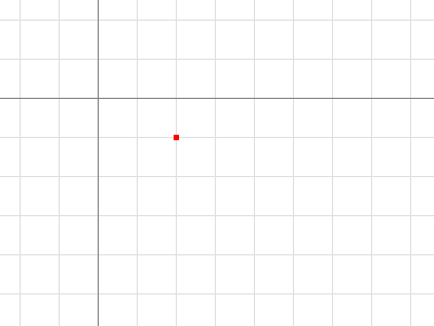
A Point is an X, Y coordinate pair. The axes increase right and down (origin = top left corner). It is neither a pixel nor a grid square. A Point has no intrinsic width, height or color, but the visualizations below use a small colored square.

p := image.Point{2, 1}
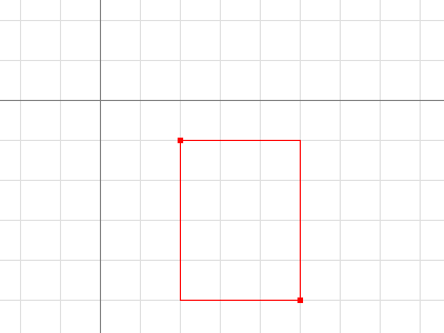
A Rectangle contains the points with Min.X <= X < Max.X, Min.Y <= Y < Max.Y. It has no intrinsic color, but the visualization below outlines it with a thin colored line, and call out their Min and Max Points.

r := image.Rect(2, 1, 5, 5)
For convenience, image.Rect(x0, y0, x1, y1) is equivalent to Rectangle{Point{x0, y0}, Point{x1, y1}}, but is much easier to type. It also swaps Minimum and Maximum to ensure it’s well formed.
That’s it. Let’s look at the code:
Code
layout.Rigid(
  func(gtx C) D {
    circle := clip.Ellipse{
       // Hard coding the x coordinate. Try resizing the window
       // Min: image.Pt(80, 0),
       // Max: image.Pt(320, 240),
       // Soft coding the x coordinate. Try resizing the window
       Min: image.Pt(gtx.Constraints.Max.X/2-120, 0),
       Max: image.Pt(gtx.Constraints.Max.X/2+120, 240),
    }.Op(gtx.Ops)
    color := color.NRGBA{R: 200, A: 255}
    paint.FillShape(gtx.Ops, color, circle)
    d := image.Point{Y: 400}
    return layout.Dimensions{Size: d}
  },
),
Comments
We first define a circle using clip.Ellipse{ }. It defines circle as an Ellipse within a box, where the dimensions of the box are specified by the top left and bottom right corners. Min and Max respectively.
By choice there are two versions of Minand Max. One is hard coded, just to show how image.Pt( ) works. But that might not necessarily be what you want - try it for yourself by changing what’s commented in and out and resize the window.
Instead, dynamic positioning based on gtx.Constraints adapts to the window. Play around with these dimensions, familiarize yourself with when the circle moves up or down, depending in wheiter you resize the window or move the limiting box around the Ellipse.
Gotcha: If you are lucky enough to work with a High DPI display, and happen to run it with a scaling factor of, say 125%, another problem with the hard coded coordinates will surface. Gio works well with Dp, Display independent pixels, which ensures that 1 Dp will have the same apparent size across displays and resolutions. When hard-coding like here, that dynamic is overruled. A 125% resolution scale will translate the 400 Dp wide window (as defined in app.NewWindow) into a 500 pixels context. You can see this by inspecting gtx.Constraints and convert pixels to Dp by gtx.Dp().
color.NRGBA defines the color of the circle. Note that the Alpha-channel defaults to 0, i.e. invisible, so we lift it to 255 so we can actually see it.
paint.FillShape fills the shape with the color.
And finally we return the widget in the form of its Dimensions, height: 400.